First Class Aircraft seat Repair (Ported from Internship Report)
3.2 AIRCRAFT SEAT WIRING PROJECT
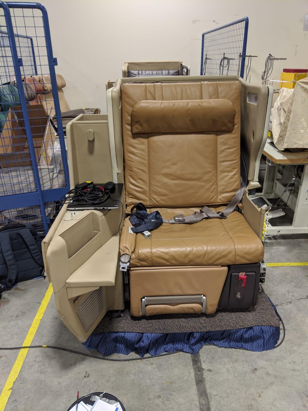
When I was first introduced to the project, there were 2 chairs, where one had wiring that was already completed, with only a few problems and a second chair where the wiring had not been done.
During the first few days of the project, I spent time studying and learning more about the limits and power input required for the actuators that move the back and leg rests.

Above in the image included is the wiring diagram for all the wiring involved in the aircraft seat. MS03,MS04,MS05,MS06 refer to the microswitches located in the switchboard. MS01,MS02 refer to the microswitches used as limiting switches for the back rest actuator. R01-R04 refer to the 4 specialised transistors used to dictate which microswitches would supply power to which direction of actuation of the individual actuators.
As I started on wiring for the chair, I split the work into 3 sections. Section 1: wiring on the microswitch board, Section 2: Wiring for the Actuators and Section 3: Wiring for limit switches
SECTION:1 Switchboard wiring

One of the major problems on the seat is that the original wiring power supply was designed to run off Aircraft AC power. As the chair was intended to be run on regular 120Vac wall power. As such, a custom Power supply (in the image above) was needed as the internal power supply located in the chair would not work on wall power.

As a result of the power supply change, most of the wiring included in the seat had to be redone or customized. Firstly, the original switches located on the switchboard (in the image above) to control the actuators were changed. I took all the old microswitches off the original switchboard and cut 4 holes in it to mount the new Microswitches. The 4 switches are connected to 4 transistors to prevent the microswitches from being fried by the high voltage needed for the actuators.
Additionally, I was asked by my supervisor to add functionality for turning on the reading lights on the seat.
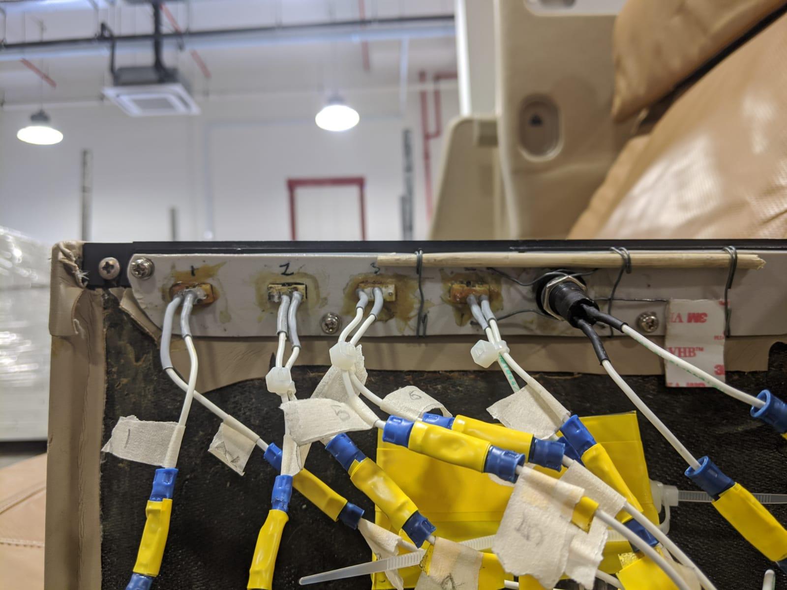
Firstly, I had to add a button to the switchboard. The image above shows the modified switchboard. I purchased a simple latching switch to simulate the turn on/ off functionality of the light switch. Next, I cut a hole in the board to fit the latching switch through. I encountered the problem of the board flexing too much when the button is pressed. To remedy this, I came up with the solution of adding 4 holes around the switch, forming a rectangle, and threading steel wire through them to tie to the latching switch and add rigidity to the switch as well as the board. To further boost rigidity, I took a thin wood stick and tied it down to the board using more steel cable, it served well in making the board more rigid overall and ensuring the switch functions properly.
SECTION 2: Actuator Wiring
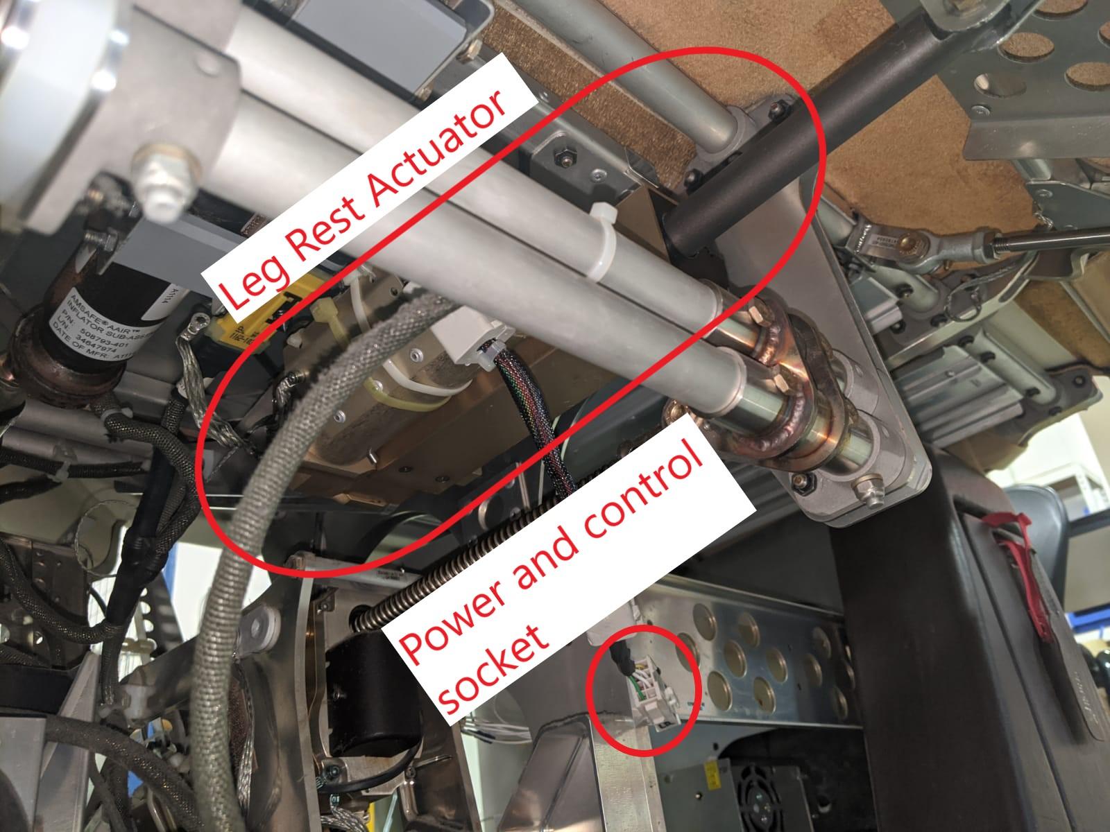
For the wiring of the actuators, I had to add pin connectors onto the ends of the power carrying wires to allow for adaptability with the power and control sockets on the actuators. In the image above, the Leg rest actuator is circled on the top. The leg rest actuator can push and pull, with a physical switch on the side that disables the ratcheting system to allow for it to be fully retracted or fully extended by hand without the use of any power supply.
However, the back-rest actuator has the capability to extend and retract, however it lacks the capability of having a physical switch to disable the ratcheting mechanism. This is due to the fact that even with the mechanism disabled, the entire back rest is too heavy to be moved by hand as the back rest adjusts its angle by moving the seat cushion forward, meaning that there are multiple moving parts involved that would simply not be moveable by hand.
All the actuators are grounded using the grounding slot on the power supply and the shell of the actuators are also grounded to the frame of the entire seat.
SECTION 3: Limit Switches
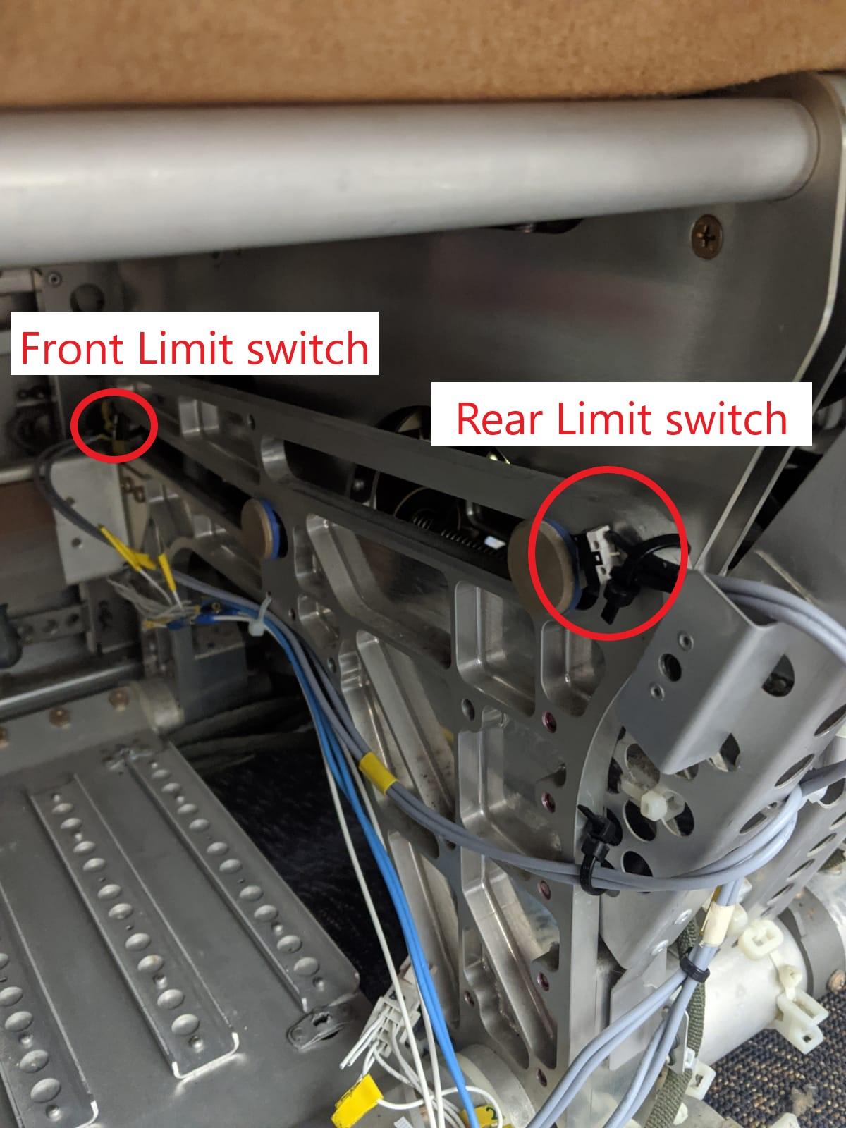
The limit switches serve to prevent the Actuators from damaging the entire system by cutting off the power to the Actuators once they come into contact. In the image above, the rear limit switch is being engaged, meaning that if the backward moving backrest button were pressed, it would not power the actuator. Vice versa, the front limit switch is unengaged, thus if the forward moving backrest button were pressed power would be supplied to the actuator.
Comments
Post a Comment