Posts
First Class Aircraft seat Repair (Ported from Internship Report)
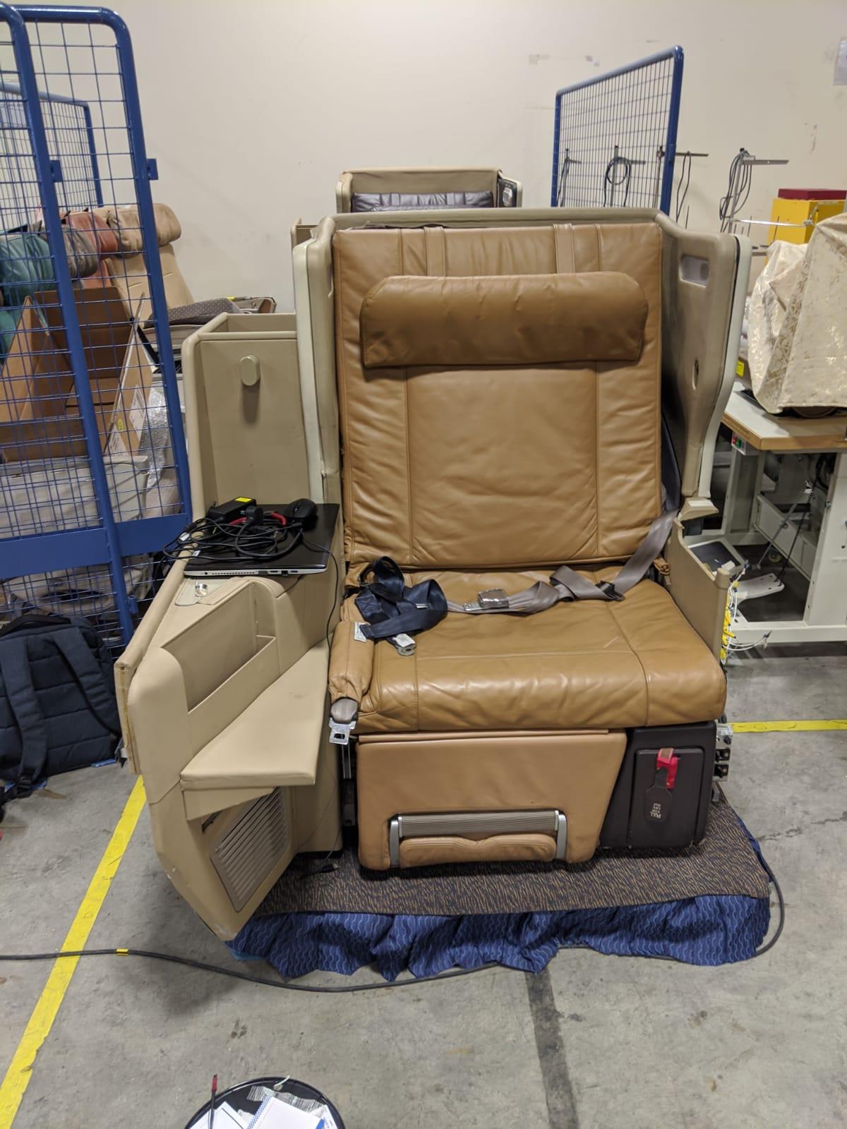
3.2 AIRCRAFT SEAT WIRING PROJECT When I was first introduced to the project, there were 2 chairs, where one had wiring that was already completed, with only a few problems and a second chair where the wiring had not been done. During the first few days of the project, I spent time studying and learning more about the limits and power input required for the actuators that move the back and leg rests. Above in the image included is the wiring diagram for all the wiring involved in the aircraft seat. MS03,MS04,MS05,MS06 refer to the microswitches located in the switchboard. MS01,MS02 refer to the microswitches used as limiting switches for the back rest actuator. R01-R04 refer to the 4 specialised transistors used to dictate which microswitches would supply power to which direction of actuation of the individual actuators. As I started on wiring for the chair, I split the work into 3 sections. Section 1: wiring on the microswitch board, Section 2: Wiring for the Actuator...